This post will introduce basic I/O (Input and Output) with Intel Galileo. Besides we will also introduce digital and analog pins. Figure below shows digital and analog pins of Galileo.

Activity 1
A. How many digital pins are available on Galileo?
B. How many analog pins are available on Galileo?
1. Digital Pins
In this guide, we will explore pinMode(), digitalRead and digitalWrite APIs.
1.1 pinMode()
We use pinMode() to configure the specified pin either to behave as an input or an output.
Syntax
pinMode(pin, mode)
where:
pin: the number of pin to set.mode: INPUT, OUTPUT, or INPUT_PULLUP.- return: node.
1.2 digitalRead()
digitalRead() is used to read the value from specified digital pin.
Syntax
digitalRead(pin)
where:
- pin: the number of digital pin to read.
- return: HIGH or LOW.
1.3 digitalWrite()
digitalWrite is used to write a HIGH or LOW value to a digital pins.
Syntax
digitalWrite(pin, value)
where:
- pin: the pin number to write to.
- value: HIGH or LOW
Activity 2
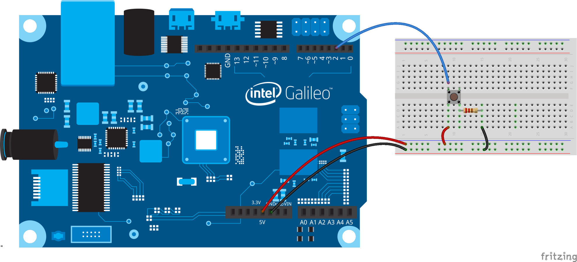
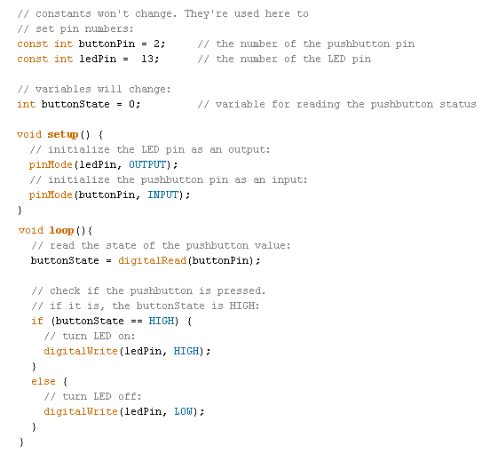
Turn off a built-in LED of Galileo (pin 13) while pressing the pushbutton (pin 2).
Hook up and assemble the components as shown below:
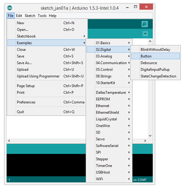
Open Button (File > Examples > 0.2 Digital > Button) example.
Source code:
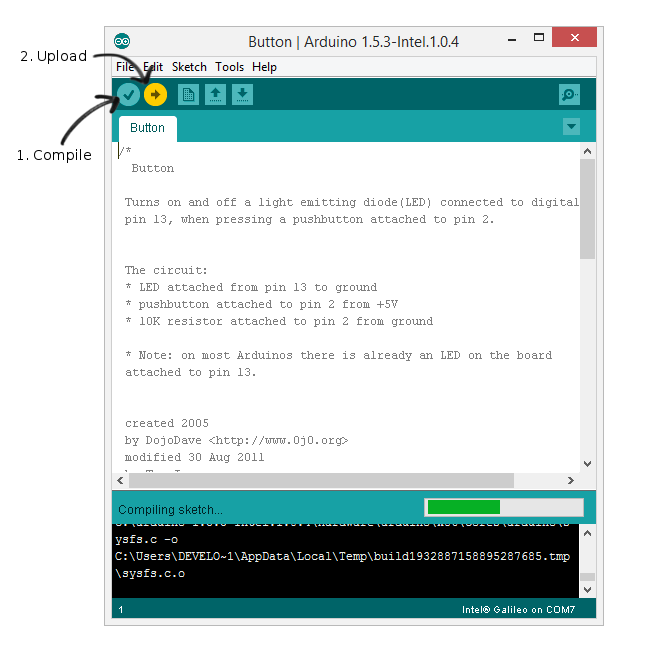
Compile and upload the sketch.
Press pushButton and observe either that action turns on or turn off the built-in LED.
A. When button is pressed, LED turns ___
B. When button is released, LED turns ___
Activity 3
Print out the value of pushButton through Serial Monitor.
Hint:
Use Serial API to display output in Serial Monitor.
- Add
Serial.begin(9600);in Setup function. - Add
Serial.print(buttonState);in Loop function.
A. What is the value of buttonState when button is not pressed? ___
B. What is the value of buttonState when button is pressed? ___
1.2 INPUT_PULLUP
Pin default as INPUT. So When pin is disconnect, it randomly read HIGH and LOW. For Example, when wiring buttons or switches or anything that “normally open”, we have to tie them to the ground. A 10K Ohm resistor can acts as pull-down resistor for digital input pin.
Activity 4
Turn on the built-in LED (pin 13) while pressing pushButton (pin 2).
Hook up all components as shown below:
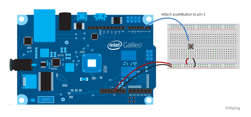
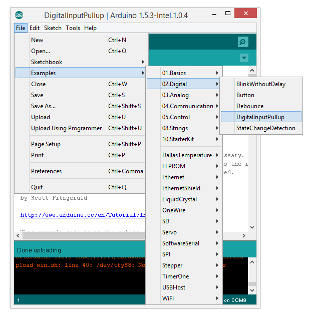
Open Button (File > Examples > 0.2 Digital > DigitalInputPullup) example.
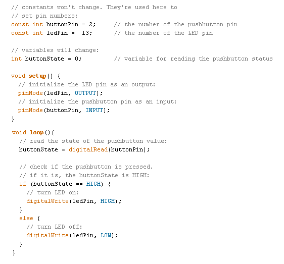
Source code:
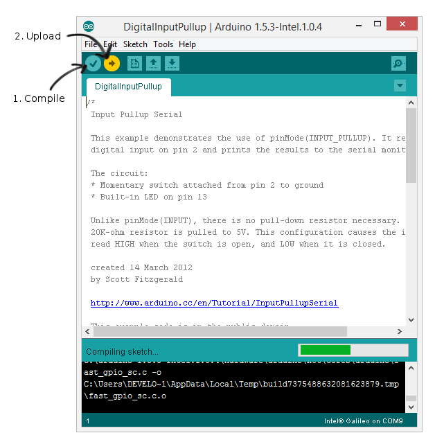
Compile and upload the sketch.
Press pushButton and observe either that action turns on or turn off the built-in LED.
A. When button is pressed, LED turns ___
B. When button is released, LED turns ___
2. Analog Pins
In this guide, we will explore analogRead() and analogWrite() APIs.
2.1 analogRead()
We use analogRead() to read the value from the specified analog pin.
Syntax
analogRead(pin)
where:
pin: the number of analog pin to read.- return value: int (0 to 1023)
2.2 analogWrite() (PWM)
We use analogWrite() to write an analog value (PWM wave)to a pin.
Syntax
analogRead(pin, value)
where:
pin: the number of analog pin to write to.value: the duty cycle (between 0(always off) and 255(always on)).- return: nothing.
2.1 PWM (Pulse-Width-Modulation)
Description
In simple description, PWM produces output analog results but with digital means and PWM is not a pure analog output.
Activity 5
Use PWMto fade the LED.
Hook up all components as shown below:
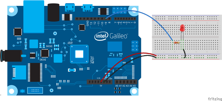
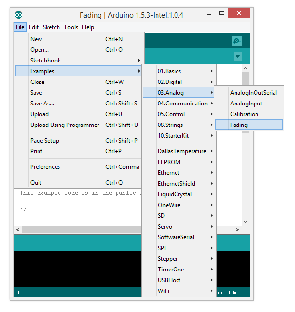
Open Button (File > Examples > 0.3 Analog > Fading) example.
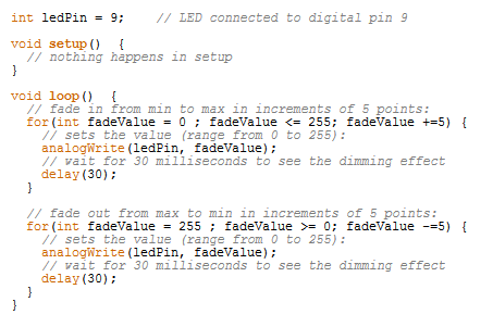
Source code:
Compile and upload the sketch.

Observe the fading of the LED. Explain how the source code works.
Activity 6
Use potentiometer to fade the LED.
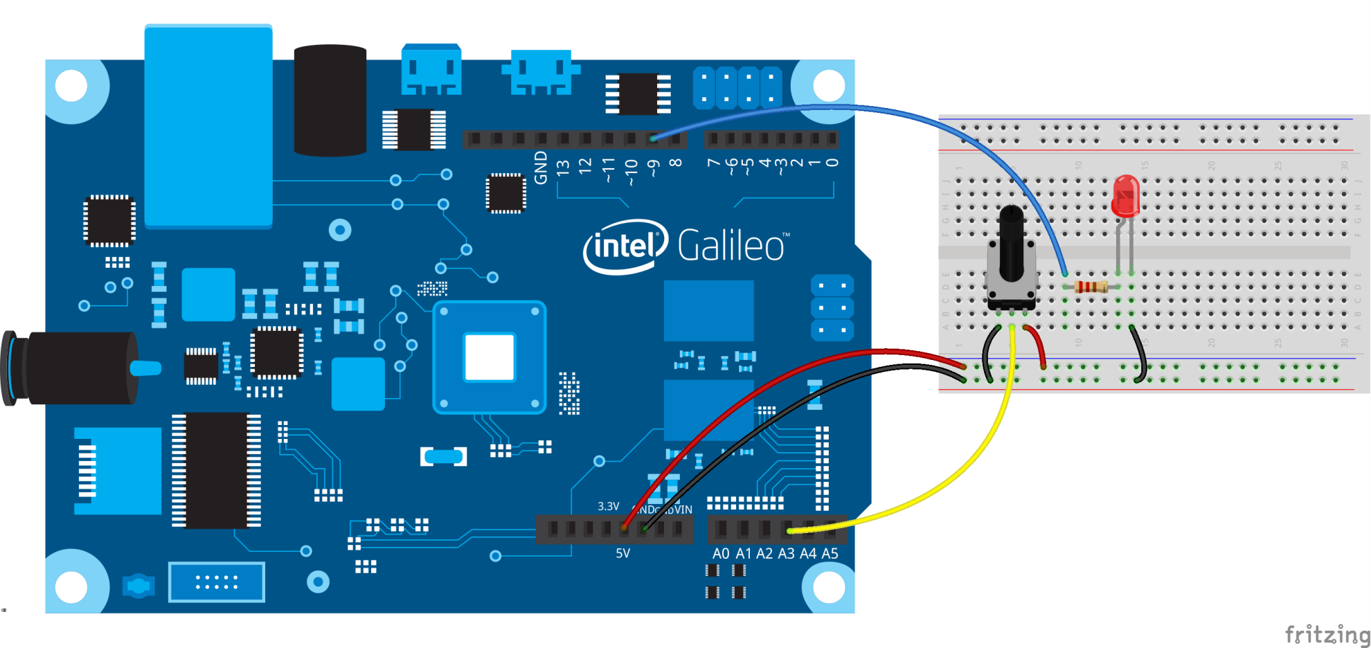
Potentiometer has 3 pins:
- Pin 1: connect to GND
- Pin 2: connect to analog pin 3
- Pin 3: connect to 5V
Hook up the components as shown below:
Source code:
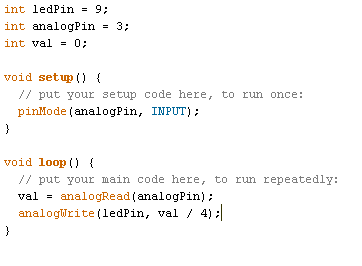
Compile and upload the sketch.
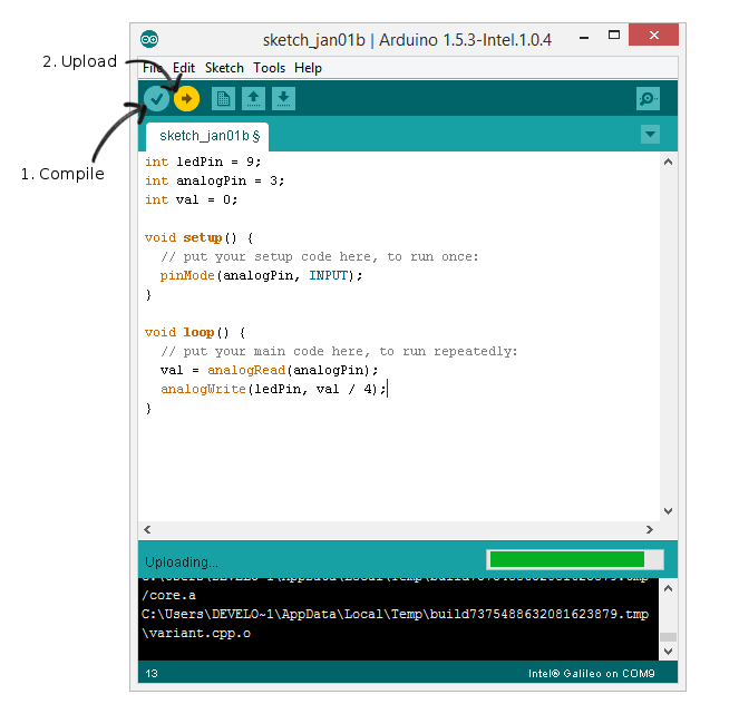
Fade in and out of LED using potentiometer.
A. Refer source code, at line analogWrite(ledPin, val / 4);, why we divide val by 4? ___
Small Project
Blink an LED with pushButton. While pressing the pushButton, the interval of the blinking should be adjustable by potentiometer. Once you release the pushButton the LED should turns off.

blog comments powered by Disqus